
3d Printer - part 7
Progress continues on my 3d printer...
Power Supply
Meters for my power supply arrived a few weeks back, but I only just got around to installing them. I had to drill out a 38mm hole for the mechanism to fit inside of, but I only have 45mm+ hole saws and 32mm spade bits, which made things a bit complicated. If only I had a CNC machine, this would be a piece of cake! For some reason that did not occur to me and instead I used a 32mm spade bit followed by a few minutes on the Dremel with a sanding disk. Did the job pretty well, even if it did cover the garage in MDF dust.
A couple of hastily drilled mounting M3 holes and a whole lot of epoxy leaves this:

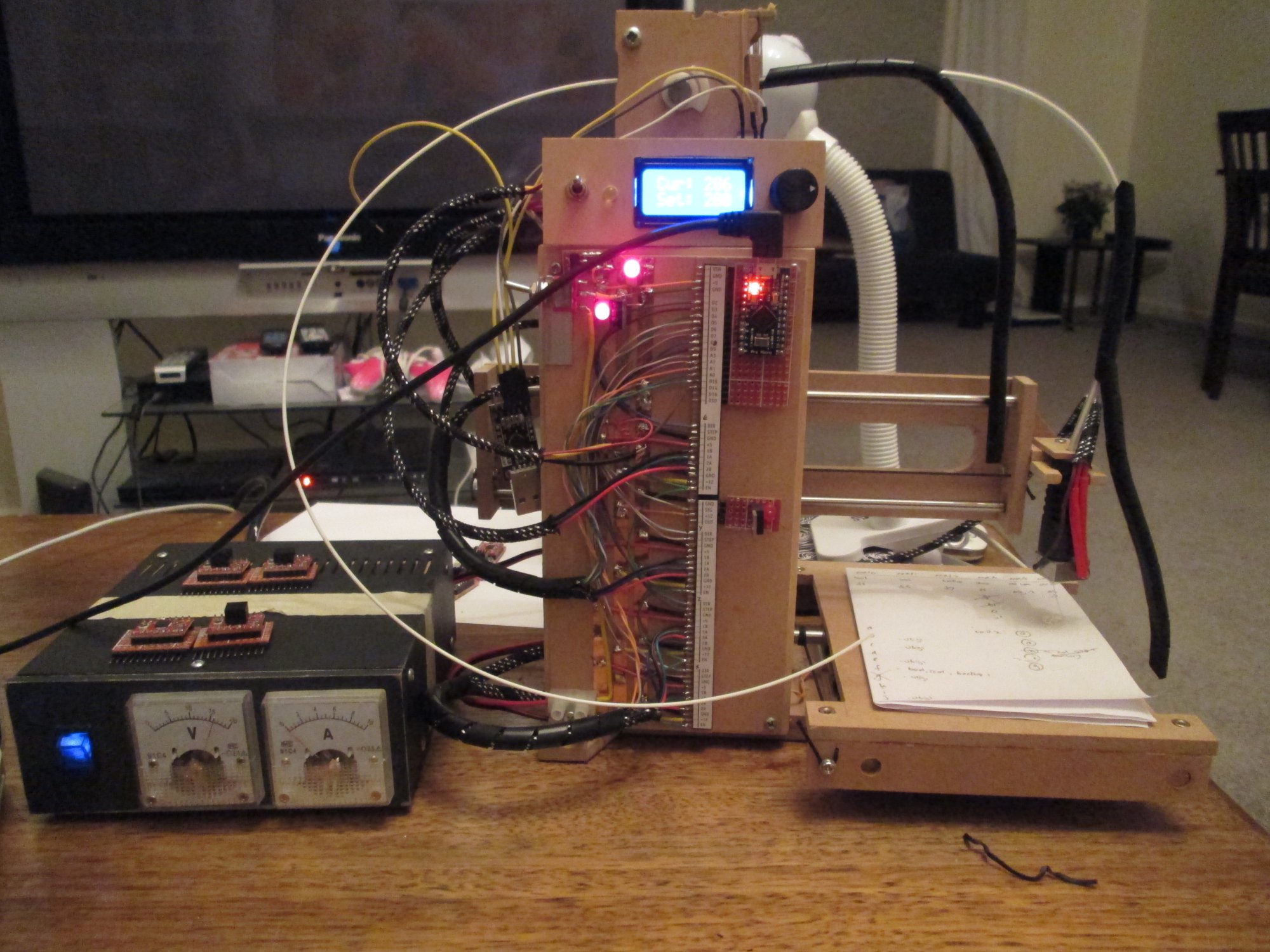
I wired the voltmeter in parallel, and the ammeter in series with the output. Nice and simple, works a treat. Completed power supply was reassembled and tested on an RCD protected output, just in case. All tests passed and the meters were even wired up correctly.
Printer
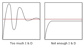
Testing showed that the heating controller remains unreliable, always overshooting the initial set point by sometimes up to 50%. I thought about it some more and realised that if I were the PID controller, I'd almost solely use the error input to determine the output; in PID terms that meant a lot of P (for proportional) and no I (for integral) or D (for derivative). I programmed that into the controller and suddenly, almost perfect! It never quite reached the target value, which means I just need a bit of I or D... which one of the two beats me, maybe if control systems hadn't been such a yawn at uni I'd have more of an idea.
Here is a fancy diagram of two different PID configurations, showing an underdamped system on the left, and a underdamped system on the right. Somehow I need a combination of the two... or I can just set the set point 10°C higher on the righthand side and be done with it? Watch this space as I play PID theory.
Meanwhile all 7 replacement step sticks arrived; 4x A4983's, and 3x A4988's. With the Dremel I quickly sliced up 7 carrier boards and in a marathon soldering session completed the 189 solder joints required to connect everything up. A careful visual inspection followed before testing each board in the 3d printer.
After testing each stepstick it was time to do a complete system test. That meant checking each axis moved in the expected direction, and by the right amount. Some careful testing with a ruler and calculator followed, and over a few iterations I managed to get the control parameters honed in.
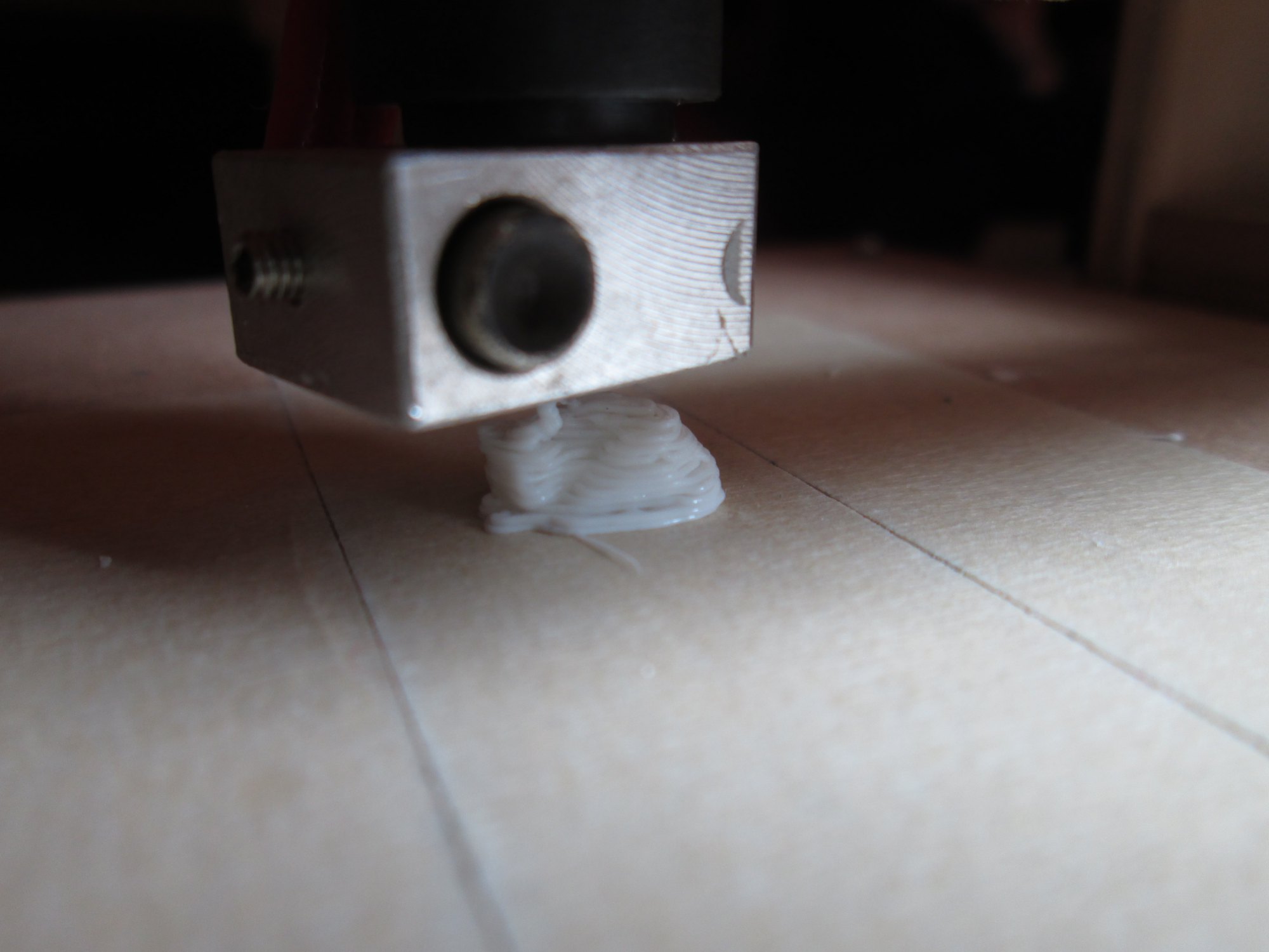
A bit more testing and it was time to generate my first G code file. I fired up Slic3r to slice the model into layers and then proceeded to print! A few problems immediately cropped up, such as no plastic coming out, and the motors losing steps during rapid moves. The latter was easily fixed by tweaking the maximum travel speeds in Teacup (the code the Arduino runs to convert computer commands into motor movements), while the former was fixed after some fiddling by making the extruder motor shaft "grippier".
A bit more testing and some head scratching over the homing routine followed. I now realise that simply manually positioning the extruder in the center of the platform and issuing a G92 X50 Y50 Z0 command will tell Teacup that the current location corresponds to X=50, Y=50, Z=0 which is where Slic3r positions the model.
So with all that solved, I present the first item out of my printer:
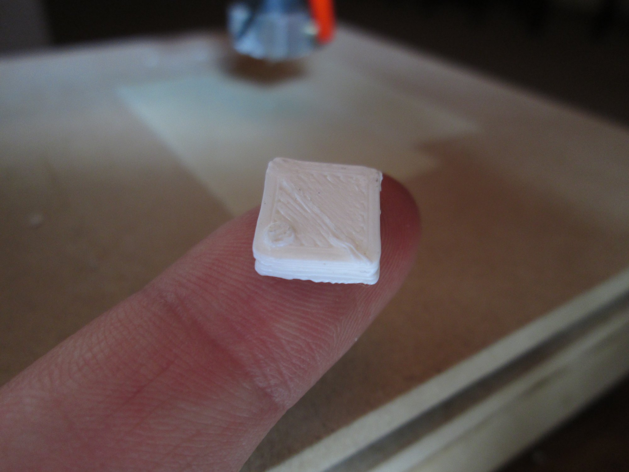
It won't win any prizes for accuracy or quality, however it is roughly square. Another issue that cropped up is "ooze", where the nozzle continues to ooze molten plastic, even while it shouldn't be. Some late night reading showed this to be a common problem and fixable by automatically reversing the extruder when moving, which draws the filament back out of the heating chamber, "sucking" the molten plastic back inside. Seems to work pretty well.
I made another tweak to the extruder, lapping the shaft with 260 grit wet & dry sandpaper, as the original grippy surface on the steel rod wasn't very resilient and had rubbed off after just one print. The new wet & dry UberGrip shaft however grips the filament much better. A slight increase in motor current to the extruder and missed steps
So tonight I loaded up an old favourite, the 3d cat model. I set the scale for 40% to do a nice quick test, homed the axis with a G92 command and hit print.
This went quite well, but I tweaked the settings a bit to give a faster and larger build, with a smaller layer height. Cat #2:
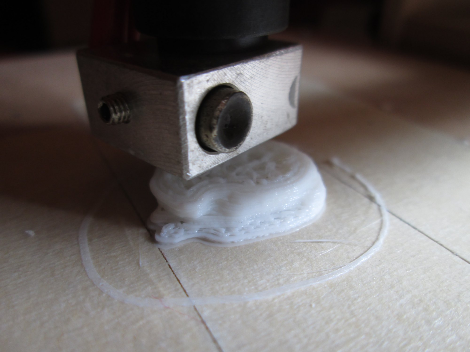
The ring around the outside is to prime the nozzle. Inside the cat you can see it's crosshatched; this is to save material but still provide some support. Seems to work well.
And the finished result...
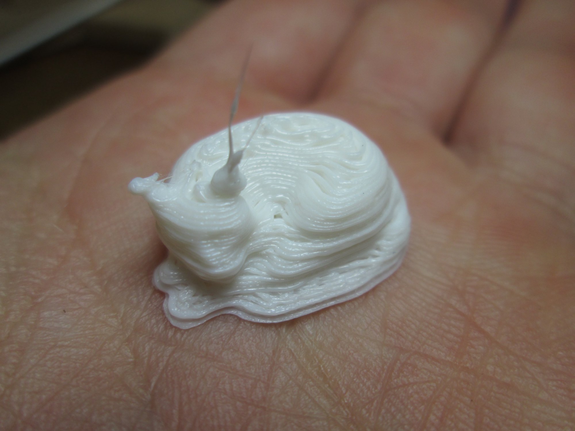
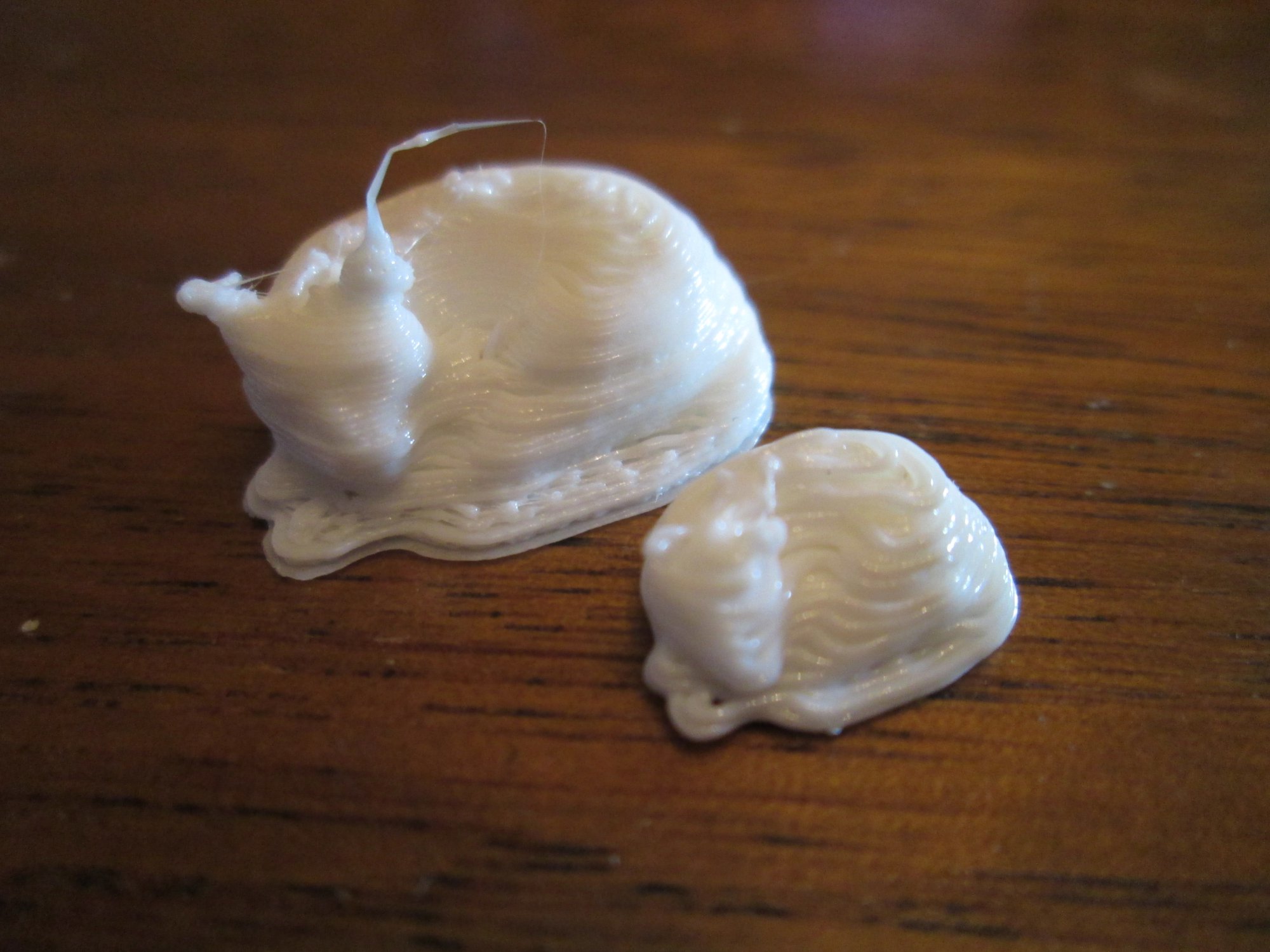
Still very rough, and a lot of tweaking needed, but it is printing! Here is a short video of it mid-print: http://www.youtube.com/watch?v=xLvyAwHKY0g. The whirring singing noise is the stepper motors tracing out complex paths, while the clicking noise is the extruder missing steps, which is now mostly fixed.
Question now is, what do I print next?
Leave a comment?