
3D Printer - part 4
Progress continues on my 3d printer. This week I have been continuing to work on the Z axis. With the rails and bearings ready I needed needed to make something to connect the threaded rod to carriage. I decided to use my tried-and-tested method of casting a white-metal block directly around the threaded rod.
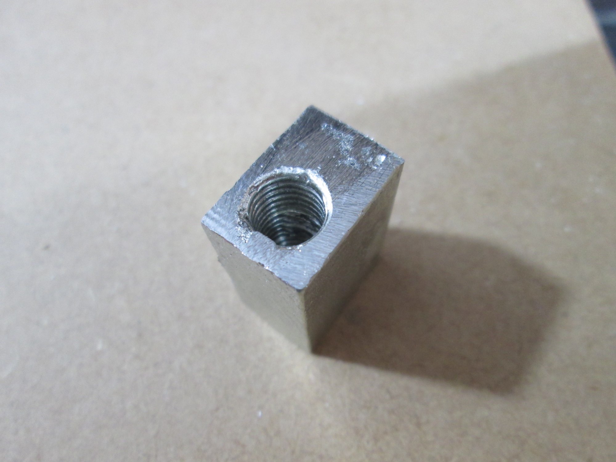
To do that, I fixed up my previous mold and found some white metal. I melted it on the stove (thanks for the tip sis!) and poured it into my mold, tapping it a few times to get rid of any bubbles. Then I pushed a block of wood down on the top and waited for it to cool. I destroyed the mold to remove my item, but never mind. I don't anticipate needing to make any more for a while. I gave it a quick clean with a file and used my drill on grunty-mode to remove the threaded rod. I gave it a zap with CRC and drove the rod through a few dozen times to clean out the thread. Here is the finished block:
I threaded it on to the rod and wondered how I was going to connect the rod to the motor, since I was still waiting on the coupling to arrive from China. (Not sure what's happening at China Post; in the past they were lightening quick, but in the last year they've become incredibly slow; last year I had a package take two months to arrive!)
But luckily while pondering this the postie arrived with exactly the part I needed! So soon enough I had the rod attached and ready for measuring. I clamped some wood over the bearings to give me a parallel line to measure to.

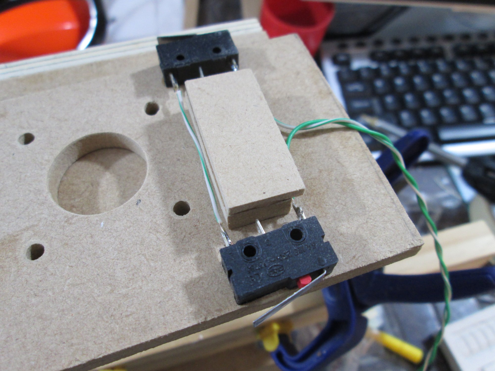
I found some wood the right size to bridge the gap and glued it in place between the limit switches.
I left that to dry overnight.
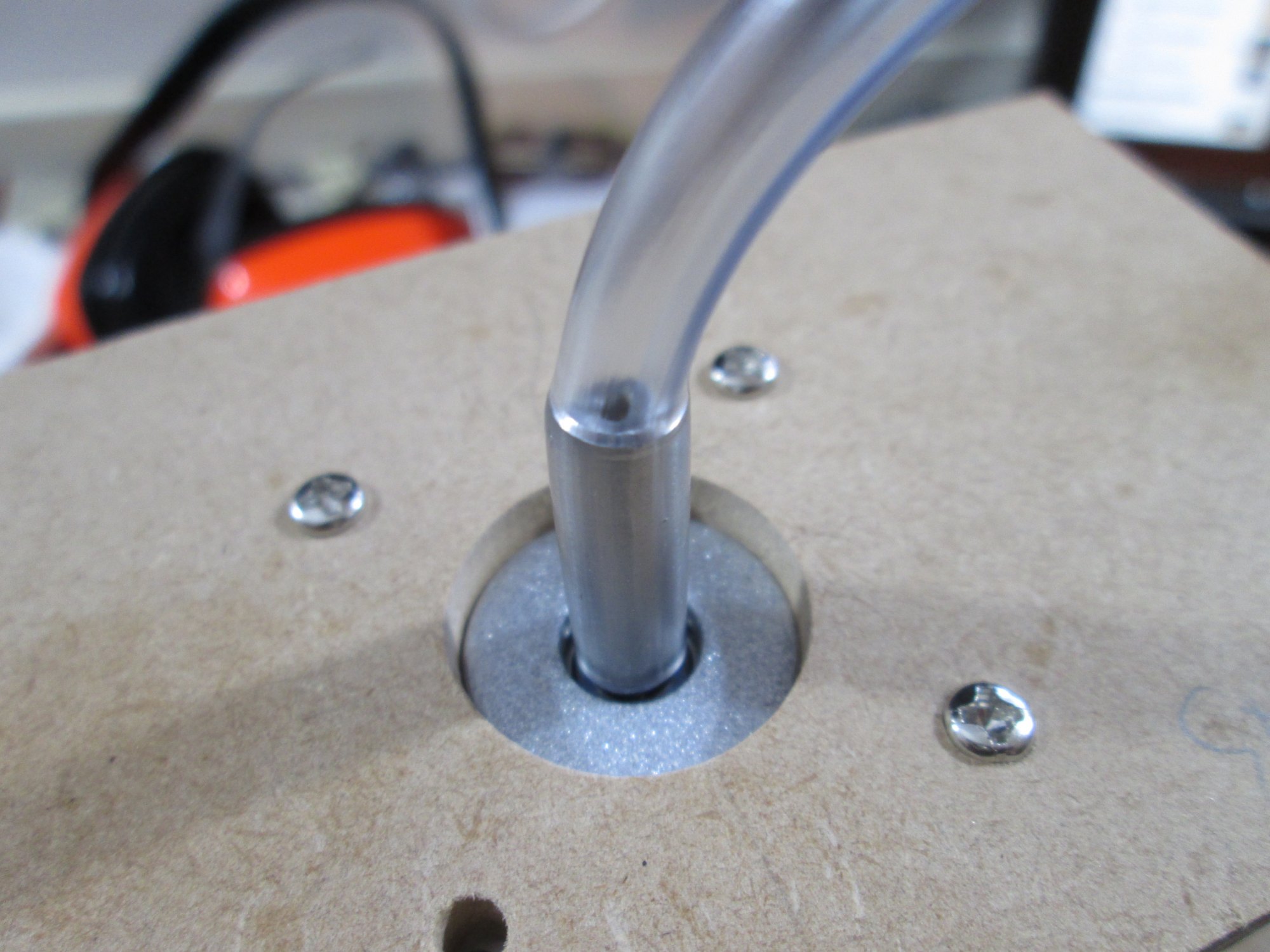
Today I bought some 5mm vinyl tube to slip over the stepper motor shafts. This increases their diameter, and makes them grippier. The reasons for this will become apparent later on. The tube was a very tight fit, but heating it made it much easier to slip on.
Then I coated everything in 5 minute epoxy and attached the Z axis carriage to the bearings.
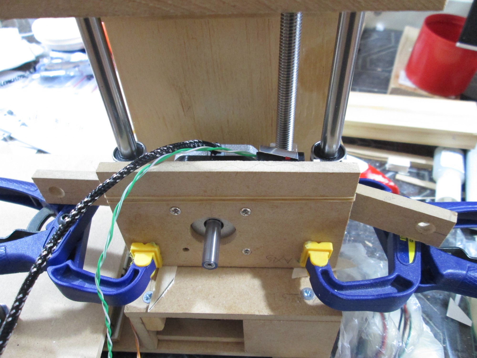
I camped the bottom bearings and used some rubber bands to clamp the upper bearings. The bits of wood sticking out the side are spacers to make sure the upper bearings didn't slide down; 5 minute epoxy has a similar consistency to golden syrup, so while sticky, it is also quite liable to slide and run. After a few hours I checked and it slides quite well, although my shaft coupler is rather lop-sided; I may need to replace it at some point.
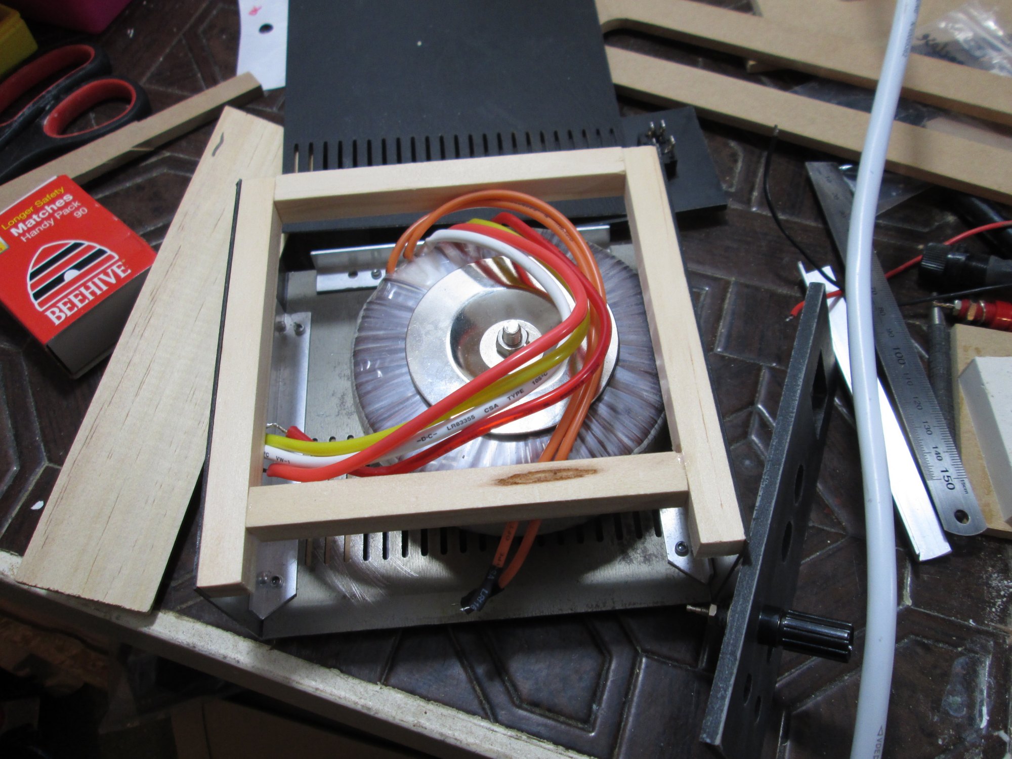
To power the printer and my CNC machine, I decided to build a proper power supply. In my box of bits I found a very solid toroidal transformer, 18V AC at 2x 4.44A, which makes a total power of 160VA. Rectified that'll give me a total output of 25V at 13A. I can't imagine every needing anywhere near that amount! I have another transformer that is 12V AC at similar ratings, which would give me a slightly more usable 17V, so I may yet downgrade to that one.
I dug out the old power supply and case I'd started to make. I quickly decided that a wooden frame & some self tapping screws would be the fastest option, much easier than trying to continue with my riveted construction.
I chopped some 1/2" wood to make up the frame and glued that into position. I found some binding posts and a nice blue illuminated power switch, plus a power socket and fuse holder. Add a rectifier and some capacitors and it'll be ready to go. Will make a nice change from having to ensure my CNC consumes < 5A (otherwise the laptop power supply I'm using with it resets!)
Hopefully in the next few days my 5 and 6mm linear bearings finally arrive; they're the only thing I'm still waiting for. Well, that and some female pin headers... I have a stack of 5 around here somewhere, but they seem to have gone missing and I suspect a fidgety kitten might have something to do with it. No doubt next time we move the fridge or oven we'll find a stash of them safely hidden away underneath!
Leave a comment?